
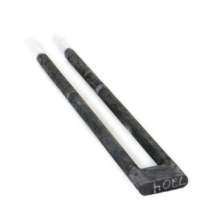
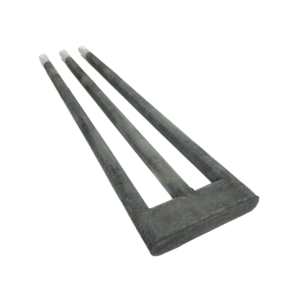
One of the earliest heating element designs, the enlarged cold ends of the Dumbbell style element were originally made oversized to increase cold end cross section, lowering electrical resistance, thereby lowering cold end operating temperature. Modern Dumbbell Starbars, by contrast, employ an advanced technology to keep the terminal ends cool by virtue of the decreased resistivity of the lower resistance cold end material used in the manufacturing process. Oversize cold ends are therefore no longer necessary. Non-dumbbell (RR Starbars) can be substituted for Dumbbell Starbars. Improvements in the cold-end-to-hot-zone resistance ratio between the original DB and new DB Starbar have been dramatic. The old style resistance ratio was 1:3, whereas the new DB and RR resistance ratio is a minimum of 1:15.
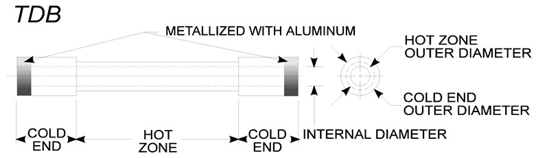
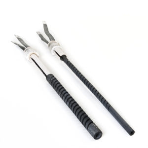
The first several inches of the cold ends are metalized with aluminum to provide a low-resistance contact surface. Electrical connections are made using flat aluminum braids, held in compression to the cold end circumference by stainless steel spring clamps.
DB Starbars are described by giving the overall length, the heating section length, the hot zone outer diameter and the cold end outer diameter.
As an example, DB 22 x 15 x .31/.50 is a Dumbbell Starbar 22 inches long, 15 inch hot zone, .31 hot zone OD and .50 cold end OD. In millimeters the part number would be DB 560 x 380 x 8/14.
For sizes available, please refer to Table B, DB Starbar Dimensions.
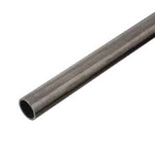
With a larger diameter, thinner wall, and clear inner diameter (ID) the TDB are used as tube heaters. An electrically insulative load tube, usually made of mullite, can be used to isolate the product from the TDB Starbar. The surface of Starbars are electrically live. See Table B, for the ID dimensions and recommended load tube diameters.
TDB Brochure
Jump to section
Sizing Breakdown
| Item # | Diameter | Maximum Hot Zone Length | Maximum Cold End Length | Hot Zone (Electrical Resistance) | Cold End (Electrical Resistance) |
|---|---|---|---|---|---|
| TDB-1.12-30 | Type TDB Tubular Dumbbell - (Enlarged Cold End) - Silicon Carbide Heating Element | 1.12 Inch 30 mm | 1.50 Inch 38 mm | 24 Inch 610 mm | 40 Inch 1016 mm |
| TDB-1.63-40 | Type TDB Tubular Dumbbell - (Enlarged Cold End) - Silicon Carbide Heating Element | 1.63 Inch 40 mm | 2.00 Inch 50 mm | 24 Inch 610 mm | 40 Inch 1016 mm |
| TDB-2.00-50 | Type TDB Tubular Dumbbell - (Enlarged Cold End) - Silicon Carbide Heating Element | 2.00 Inch 50 mm | 2.38 Inch 60 mm | 24 Inch 610 mm | 40 Inch 1016 mm |
Mounting
Walls or in ceramic lead-in sleeves, if used, must be large enough to ensure no physical binding of the Starbars. The alignment of the support holes through refractory walls should also guarantee that no physical binding occurs.
If ceramic fiber bulk is used to help reduce radiant energy losses around the Starbars, it must be tucked gently around the diameter of the cold end for a distance of only 12 mm (1/2 inch). The ceramic fiber should never be packed so tightly that it restricts the thermal expansion differences between the Starbar and furnace components. Aluminum braid should be kept slack so that there is no physical stress being applied to the Starbars.
TABLE C
Recommended Minimum Refractory Hole Size
Minimum Hole Diameter Based on Refraactory Wall Thickness
Specifications
Operating Temperatures
DB Starbars can operate to furnace temperatures up to 2730ºF (1500ºC). If the furnace temperature is to be 2600ºF (1425ºC) or above, the terminal end or cold end should be well protected within the refractory wall of the furnace. The hot zone material is rated to furnace temperatures up to 3100ºF (1700ºC).
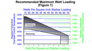
The maximum operating temperature should be reduced for non-air applications with the exception of argon and helium that can be used without any reduction. Reducing atmospheres, such as hydrogen or disassociated ammonia, particularly with low dew-points, may remove the protective silicon oxide protection that forms on silicon carbide. In such atmospheres, temperature reductions are required as shown in Figure 1.
The maximum furnace temperature for a nitrogen atmosphere is 2500ºF (1370ºC) with a watt loading of 20 w/in2 to 30 w/in2 (3.1 w/cm2 to 4.6 w/cm2) maximum watt surface watt loading. Too high a surface temperature will result in formation of silicon nitride causing a thermally insulative layer to form around the Starbar resulting in over-temperature damage.
Engineering Information
Superior Performance
A 2.4 gm-cc density helps prevent the crystalline lattice structure from being oxidized, resulting in a very slow aging characteristic.
Interchangeability
Starbars are interchangeable with all dumbbell silicon carbide heating elements manufactured in the United States as well as higher resistance heating elements manufactured for the Asian and European markets. It is important to provide the nominal electrical resistance when ordering Starbars.
Electrical Characteristics
The silicon carbide Starbar is a linear type resistance heater that converts electrical energy to heat energy – Joule’s Law W = I2 x R, (W = power in watts, I = current in amperes, R = resistance on ohms).
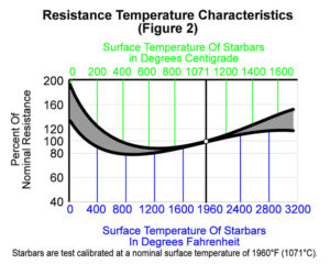
DB STARBAR has a negative
Electrical Loading
Starbars are not sized to a specific wattage output like metallic heating elements. The amount of energy that a Starbar is capable of converting from electrical to heat energy depends on the ambient furnace temperature and atmosphere in which the Starbar
Ease of Replacement
DB Starbars can be replaced while the furnace is at operating temperature. The power to the Starbars being changed should be shut off, the spring clips and aluminum braid released, and the old Starbar removed. The new Starbar should be inserted smoothly through the hot furnace with sufficient speed to insure that the aluminum is not melted off the terminal end but not so fast as to cause thermal shock.
Service Life
Starbars increase gradually in resistance with use. This characteristic of increasing in resistance is called aging. Aging is a function of the following:
- Operating temperature
- Electrical loading – usually expressed in watts per square inch or watts per square centimeter of Starbar radiating surface
- Atmosphere
- Type of operation (continuous or intermittent)
- Operating and maintenance techniques
AvailabilIty
Starbars can be shipped from stock, or two to three weeks after receipt of an order.
Specifications and Matching
Starbars have a manufactured tolerance of plus or minus 20% on the nominal resistance. All Starbars are calibrated at least twice prior to shipping to ensure their being within specifications. The calibrated amperage of each Starbar is marked on the carton and collar end of each Starbar. When installing, arrange Starbars with amperage values as close to each other as available. Longer service life will be obtained when series connected Starbars are matched in resistance. Starbars are shipped as closely matched as possible.
Furnace Heating Chamber
The furnace heated chamber dimension, which the Starbar spans, can be the same as the Starbar hot zone as shown in Figure 3 below). Recommended terminal hole diameters for various refractory walls can be calculated by increasing the Starbar outer diameter by 10%. As an example, a 1.25″ diameter SEU Starbar would require a 1.38″ terminal hole (1.25 x 1.10 = 1.38). In metric, a 32 mm diameter SEU Starbar would require a 35 mm terminal hole (32 mm x 1.10 = 35 mm).
Electrical Connections
Held in place by clamps, braided aluminum terminal straps in 25, 50, 100, and 200 ampere ratings, are available in two primary styles: Single Loop (for connecting binding post to element) and Double Loop (for connecting element to element). Post to Post straps are also available. Detailed descriptions and part numbers can be found in our accessory literature.
Terminal Clamps
There are two type of clamps: Type “M” (derives its name from its similarity to the letter M) and Type “T” (used with a tool). Please refer to our accessory literature for a detailed part number and description.
DB Starbar Spacing
X = 2 x Starbar hot zone diameter is the minimum, 1.5 x Starbar hot zone diameter is the absolute minimum and requires a reduced Starbar Surface Watt Loading.
Z = S ÷ 1.73 minimum for moving loads
S = 2 x Starbar hot zone diameter minimum
X – distance from the centerline of Starbar to any reflecting surface, such as a refractory wall or product
Z – distance from the centerline of the Starbar to a moving or stationary load
S – distance from centerline of the Starbar to the centerline of an adjacent Starbar
REQUEST INFORMATION