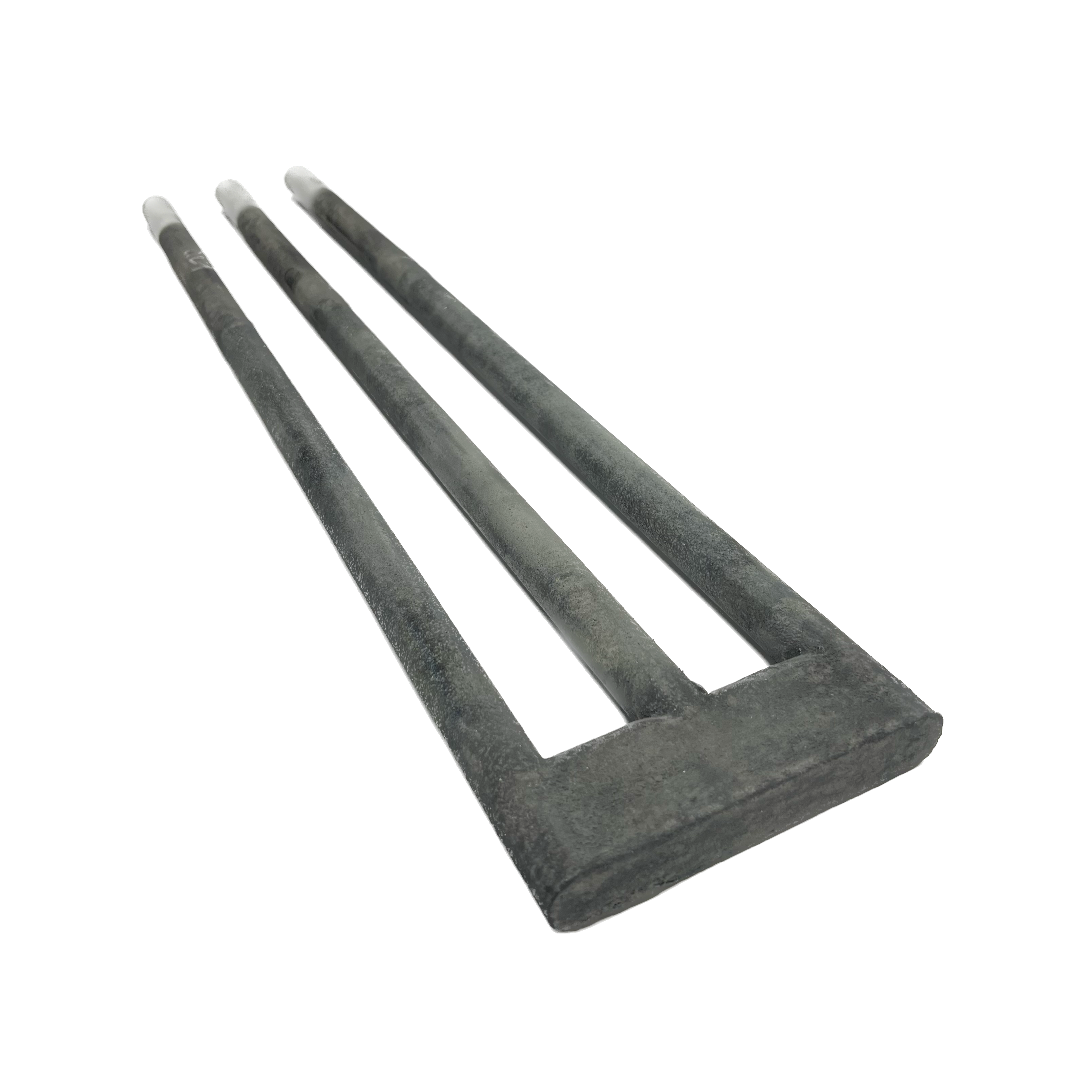
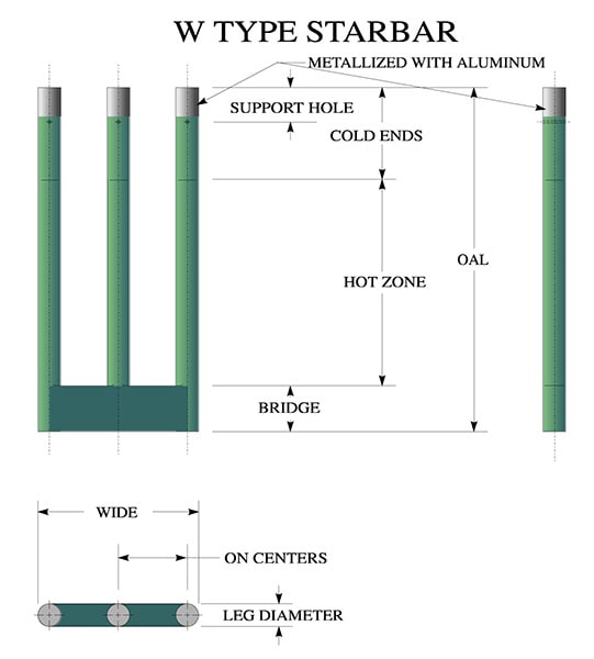
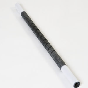
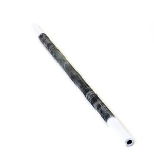
Made of high density recrystallized silicon carbide, these multiple leg Starbars use the same hot zone and cold end material as the RR type Starbars and offer a configuration that allows the electrical connections to be made at one end. The low resistance terminal ends allow for cool operation. The LRE (low resistance ends) have a high (15:1) electrical resistance ratio to the hot zone section. The first several inches of the cold ends are metallized with aluminum to provide a low electrical resistance contact surface. The electrical connections are made using flat aluminum braids held in compression to the circumference by a stainless steel spring clamp. W type Starbars are described by giving the overall length, the heating section length, the cold end length and the diameter. As an example - W 23.5 x 12 x 9.5 x 1 is a Starbar 23.5" overall with a 12" hot zone, 9.5" cold ends and 1" in diameter (W 597 x 305 x 241 x 25 is a Starbar 597 mm overall with a 305 mm hot zone, 241 mm cold ends and 25 mm diameter).
Type U&W Brochure
(PDF, 3842KB)
Jump to section
Sizing Breakdown
| Item # | Item Name | Starbar Nominal Leg Diameter | Ohms per Leg Hot Zone | Ohms per Leg Cold End |
|---|---|---|---|---|
| W-1/2-13 | W - Multiple Leg Starbars, Silicon Carbide Heating Element | 1/2 Inch 13 mm | 0.19410 Ohms/Inch 0.00764 Ohms/mm | 0.00982 Ohms/Inch 0.000387 Ohms/mm |
| W-5/8-16 | W - Multiple Leg Starbars, Silicon Carbide Heating Element | 5/8 Inch 16 mm | 0.12450 Ohms/Inch 0.00490 Ohms/mm | 0.00631 Ohms/Inch 0.000248 Ohms/mm |
| W-3/4-19 | W - Multiple Leg Starbars, Silicon Carbide Heating Element | 3/4 Inch 19 mm | 0.08790 Ohms/Inch 0.00346 Ohms/mm | 0.00433 Ohms/Inch 0.000170 Ohms/mm |
| W-1-25 | W - Multiple Leg Starbars, Silicon Carbide Heating Element | 1 Inch 25 mm | 0.05100 Ohms/Inch 0.00200 Ohms/mm | 0.00250 Ohms/Inch 0.000098 Ohms/mm |
| W-1-1/4-32 | W - Multiple Leg Starbars, Silicon Carbide Heating Element | 1-1/4 Inch 32 mm | 0.03200 Ohms/Inch 0.00126 Ohms/mm | 0.00171 Ohms/Inch 0.000067 Ohms/mm |
| W-1-1/2-38 | W - Multiple Leg Starbars, Silicon Carbide Heating Element | 1-1/2 Inch 38 mm | 0.02120 Ohms/Inch 0.00083 Ohms/mm | 0.00117 Ohms/Inch 0.000046 Ohms/mm |
| W-1-3/4-44 | W - Multiple Leg Starbars, Silicon Carbide Heating Element | 1-3/4 Inch 44 mm | 0.01650 Ohms/Inch 0.00065 Ohms/mm | 0.00082 Ohms/Inch 0.000032 Ohms/mm |
| W-2-1/8-54 | W - Multiple Leg Starbars, Silicon Carbide Heating Element | 2-1/8 Inch 54 mm | 0.01490 Ohms/Inch 0.00059 Ohms/mm | 0.00075 Ohms/Inch 0.000030 Ohms/mm |
Mounting
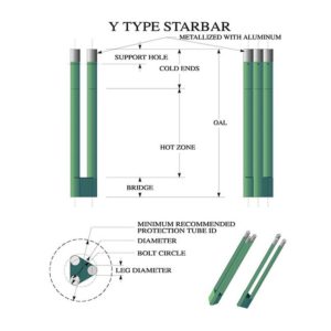
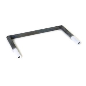
There are no restrictions on the mounting positions of Starbars, although the horizontal and vertical positions are common. The most common is vertical with the Starbar being hung from the cold ends. When these Starbars are mounted horizontally the bridge should be supported. The legs should be positioned in the same horizontal plane, not on edge. If the legs were to be positioned in a vertical plane, it would be difficult to get proper support for each leg. The Y Starbar should be mounted only vertically for the same reason. Extreme caution should be used when mounting to ensure that the Starbars are not placed in tension. There should be adequate freedom to allow for the furnace and Starbars to expand and contract independently.
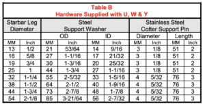
The support hardware, included with each shipment, consists of a stainless steel washer for each leg and two stainless steel cotter pins (three for the Y Starbar), as shown in Figure 3 and listed in Table B. Support hardware and support holes are not included for Starbars to be mounted horizontally.
Starbars should have their heating sections in the furnace chamber so that no portion of the heating section extends into the furnace wall or refractory plug.
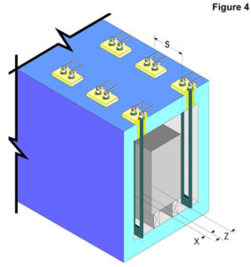
Starbars should not be placed closer than two Starbar diameters to each other or one and one half Starbar diameters to a wall or other reflecting body. If the Starbar is not able to dissipate heat energy equally in all directions, it may cause local overheating and possible failure. The formula for computing the recommended Starbar spacing to obtain an even temperature gradient on the product being heated is shown in Figure 4.
TABLE C
Recommended Minimum Refractory Hole Size
Minimum Hole Diameter Based on Refraactory Wall Thickness
Specifications
Operating Temperatures
All multiple leg Starbars can operate at furnace temperatures up to 2600 °F (1425°C). The hot zone material is rated to furnace temperatures up to 3100°F (1700°C). The restriction on the temperature relates to the terminal or cold end portion of the Starbar. If temperatures higher than 2600°F (1425°C) are required, the cold end section should be protected from the full furnace chamber temperatures.
The maximum operating temperature should be reduced for non-air applications. Only argon and helium can be used without any reduction of maximum operating temperatures. Reducing atmospheres – hydrogen or disassociated ammonia, particularly with low dew-points remove the protective silicon oxide protection that naturally forms on silicon carbide. In these atmospheres the chamber control temperature can not exceed 2500°F (1370°C).
Nitrogen atmosphere applications are limited to 2500°F (1370°C) and 20 to 30 watts per square inch (3.1 to 4.6 watts per square centimeter) maximum watt loading. Too high a surface temperature will result in a silicon nitride reaction. A thermally insulating layer forms around the Starbar resulting in very high surface temperatures which damage the Starbars.
Engineering Information
STEEL SUPPORT WASHER & STAINLESS COTTER SUPPORT PIN
Superior Performance
Starbars have superior performance due to their high density – approximately 2.52 gms/cc. This gives the Starbar very slow aging characteristics and strength.
Interchangeability
Starbars are interchangeable with all dumbbell silicon carbide heating elements manufactured in the United States as well as higher resistance heating elements manufactured for the Asian and European markets. It is important to provide the nominal electrical resistance when ordering Starbars.
Electrical Characteristics
The silicon carbide Starbar is a linear type resistance heater that converts electrical energy to heat energy – Joule’s Law W = I2 x R, (W = power in watts, I = current in amperes, R = resistance on ohms).
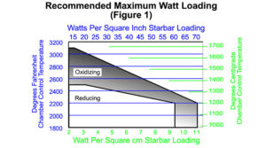
Electrical Loading
Electrical Loading Starbars are not sized to a specific wattage output like metallic heating elements. The amount of energy that a Starbar is capable of converting from electrical to heat energy depends on the ambient furnace temperature and atmosphere in which the Starbar.
Power Supply
The previous paragraph explained how to calculate the recommended wattage output of the Starbar. The following explains how to compute the electrical requirements to provide the recommended power.
Knowing the wattage output and the resistance of the Starbars supplies two parts of the three variables of the following equation: E=√ (W x R), (E = nominal full load voltage, W = rating of the Starbar in watts, R = resistance of the Starbar in ohms). The resistance of the Starbar can be calculated using the values found in Table A.
Solving for E determines the voltage required to provide the wattage output desired. This assumes a nominal resistance.
Example: A Starbar U 23.5 x 12 x 9.5 x 1 has a resistance of 1.21 ohms and 75 square inches of radiating surface. Loading to 40 watts per square inch, this Starbar could provide 3000 watts.
A Starbar U 597 x 305 x 241x 25 has a resistance of 1.21 ohms and 479 square centimeters of radiating surface. Loading to 6.3 watts per square centimeter, this Starbar could provide 3000 watts.
To find the nominal voltage solve for E.
E = √ (W x R)
E = √ (3000 x 1.21)
E = 60 volts
Starbars may be connected in parallel, series, or combination thereof. Parallel connections are preferred.
In a parallel arrangement the voltage across all the Starbars is the same. In the formula W = E2 ÷ R, (W = watts, E = voltage, R = resistance) it can be seen that the greater the resistance, the lower the wattage output. The Starbars in the parallel circuit with the lowest resistance will supply more heat energy and therefore operate at a higher temperature. This higher Starbar temperature will cause it to gradually increase in resistance until all the Starbars have the same resistance. At this time the Starbars should all have approximately the same resistance values and surface temperatures and therefore remain in balance.
To compute the network resistance of a group of Starbars, the following formula may be used: Rn = R x S ÷ P (Rn = network resistance, R = resistance of Starbar, S = number of Starbars connected in a series, P = number of parallel circuits).
Example: Eight Starbars U 23.5 x 12 x 9.5 x 1 (R = 1.21 ohms) connected 2 in series (S = 2) and 4 parallel groups (P = 4).
Rn = R x S ÷ P
Rn = 1.21 x 2 ÷ 4
Rn = 0.6 ohms
To compute the nominal voltage required to power a set of Starbars, we shall use a combination of the formulas used in the two previous examples. En = √ (Wt x Rn), (En = nominal network voltage, Wt = total wattage output, Rn = network resistance).
Example: Eight Starbars U 23.5 x 12 x 9.5 x 1 (R = 1.21 ohms) connected 2 in series, 4 parallel groups, each Starbar provides 3000 watts. Wt = 8 x 3000 = 24,000 watts, Rn = 0.60 ohms.
En = √ (Wt x Rn)
En = √ (24,000 x 0.6)
En = 120 volts
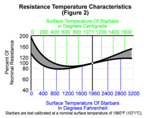
The resistance of Starbars increases gradually during their service life. Therefore some means of keeping the power input to the kiln or furnace at a level sufficiently high to maintain the desired temperature is required.
Historically, expensive voltage varying equipment such as multiple tap transformers or saturable reactors were recommended for all but the very low temperature applications.
Starbars can be used directly on the line (fixed voltages) at temperatures up to 2400°F (1315°C). To compensate for the reduced output as the Starbars gradually age or increase in resistance, the furnace or kiln is initially overpowered by 25% to 50%. This type of arrangement eliminates the expensive voltage varying equipment and has proven very satisfactory in many applications. It is not recommended when fine process temperature control is required.
Assume a furnace will require approximately 24,000 watts after all heat losses and load factors have been considered. Increasing this 24,000 by 25% to 50% gives a wattage requirement of between 30,000 and 36,000 watts.
By taking another look at the previous example of 8 Starbars, it can be seen that 10 Starbars U 23.5 x 12 x 9.5 x 1 connected two in series five parallel groups on 120 volts would supply the 30,000 watts. If 12 Starbars of the same size were used, the output would be 36,000 watts. Twelve Starbars connected four in series per phase, these three groups then in a delta, on 240 volts would make a balanced three phase 240 volt network.
The temperature of the kiln or furnace is controlled by an off-on controller. When the Starbars are new they will only be powered for 24/30 or 24/36 of the time.
As the Starbars increase in resistance they will be on for a greater percentage of the time. When they have increased in resistance to a point at which they supply 24,000 watts, they will be on 100% of the time. A SCR (silicon controlled rectifier) or thyrister can also be substituted for the contactor.
For applications where close temperature control is desired and/or for temperatures above 2400°F (1315°C) a device for increasing the voltage to the Starbars is required. There are several methods of providing this variable voltage source.
- The multiple tap transformer is the most common, because it is usually the least expensive. The secondary of the transformer is provided with taps which usually vary in number from 10 to 36. By carefully selecting the voltage taps, the correct voltage output to match the resistance of the Starbars over their complete useful life can be made.
- Saturable reactors and induction regulators are used to provide a stepless voltage control. They are also sometimes used with multiple tap transformers.
- Capacitor controls are used infrequently. They, of course, will tend to improve a power factor, which makes their use desirable in some areas.
- Silicon controlled rectifiers, (SCR) have become quite popular with the advances in solid state devices. Because of the poor power factor and other concerns regarding a large phase back, multiple tap transformers are recommended even when the control device is a SCR.
To compensate for the reduced output as the Starbars increase in resistance, a voltage range is required that will compensate for a 100% increase in the Starbar resistance. The following formula may be used to calculate Emax : Emax = √ (Wt x Rn) x 1.5, Emax = recommended maximum voltage required to compensate for increase in resistance due to aging and resistance tolerance, Wt = rating of transformer in watts, Rn = network resistance of the Starbars, 1.5 = minimum margin to accommodate the doubling of the Starbar resistance and the plus 20% resistance tolerance. A higher value will offer slightly longer usable service life.
Example: The transformer is rated at 24 KVA and has a computed nominal full load voltage of 120 volts. (Rn = 0.6, Wt =24,000)
Emax = √ (Wt x Rn) x 1.5
Emax = √ (24,000 x 0.6) x 1.5
Emax = √ (14,400) x 1.5
Emax = 180 volts
The nominal full load voltage and maximum voltage have been computed. When specifying the transformer, the nominal full load voltage is usually reduced to allow for the minus 20% resistance tolerance of the Starbars and slow furnace heatup.
To calculate the minimum voltage, take 70% of the nominal voltage. For periodic applications, take 30% of the nominal full load voltage. Auto transformers may be used if primary voltage is 230 volts or less. They should not be used in a three phase arrangement. Accepted practice limits the secondary voltage on all transformers to 300 volts. Above this, refractory voltage leakage becomes a problem.
When computing the size of the voltage steps between taps, a value of 5% of the nominal full load voltage is often used. When SCR or thyrister controls are used on the primary, fewer taps are required. For example, if 6 taps are used, the idling tap can be 0.7 x nominal voltage, then each consecutive tap would be 14% higher. For 8 taps, the idling tap would again be 0.7 x nominal voltage, each consecutive tap at 9.1% higher than the preceding value.
Ease of Replacement
DB Starbars can be replaced while the furnace is at operating temperature. The power to the Starbars being changed should be shut off, the spring clips and aluminum braid released, and the old Starbar removed. The new Starbar should be inserted smoothly through the hot furnace with sufficient speed to insure that the aluminum is not melted off the terminal end but not so fast as to cause thermal shock.
Service Life
Starbars increase gradually in resistance with use. This characteristic of increasing in resistance is called aging. Aging is a function of the following:
- Operating temperature
- Electrical loading – usually expressed in watts per square inch or watts per square centimeter of Starbar radiating surface
- Atmosphere
- Type of operation (continuous or intermittent)
- Operating and maintenance techniques
Furnace Heating Chamber
The furnace heated chamber dimension which the Starbar spans can be the same as the hot zone length of the Starbar as shown in Figure 4. Recommended terminal hole diameters for various refractory walls or plugs and Starbar sizes are shown in Table C.
Specifications and Matching
Starbars have a manufactured tolerance of plus or minus 20% on the nominal resistance. All Starbars are calibrated at least twice prior to shipping to ensure their being within specifications. The calibrated amperage of each Starbar is marked on the carton and collar end of each Starbar. When installing, arrange Starbars with amperage values as close to each other as available. Longer service life will be obtained when series connected Starbars are matched in resistance. Starbars are shipped as closely matched as possible.
Refractory Plugs
If refractory plugs are used, multiple leg Starbars can be installed from outside the furnace. A plug works the same as a large removable refractory brick. I Squared R can manufacture cast refractory plugs. If both the Starbars and the plugs are supplied, the fit between the two are guaranteed to be correct. Unless otherwise specified the material used is a 2800ºF (1535ºC) 145 pound density cast refractory. A one inch (25 mm) cross section flange is used to support the weight of the plug and Starbar. The plugs are available in both rectangular and cylindrical cross sections, see Figure 5.
Bridge Consutrction
The bridge construction of the multiple leg Starbars is unique. Unlike others available in the market, the Starbar bridge is flush, not extending beyond the hot zone diameter. Custom bridge widths are available.
Mechanical failures have historically been most frequent at or just above the bridge. The Starbar construction addresses this by eliminating any welds in this area. The hot zone material extends to the very end of the element. The bridge is two leg diameters high and is not self-heating.
Custom Configuration
Special sizes and shapes are available. For example the RU, has all the electrical characteristics of the U Starbar. The cold ends are attached perpendicular to the hot zone. The RU is normally installed with the cold end through the wall of the furnace. Special consideration must be made to keep the hot zone a sufficient distance from the hot face.
AvailabilIty
Starbars can be shipped from stock, or two to three weeks after receipt of an order.
Recommended Starbar Spacing
X = 2 leg diameter is the minimum, 1.5 x Starbar leg diameter is the absolute minimum and requires a reduced Starbar surface watt loading.
Z = S / 1.41 Minimum for Stationary Loads.
Z = S / 1.73 Minimum for Moving Loads.
S = 2 x Starbar Leg Diameter
Notes
All resistance values are +/-20%.
Support Hole diameter for all diameters is .21″ (5.3 mm)
Maximum leg diameter for Y Starbar is 1.25″ (32 mm)
REQUEST INFORMATION